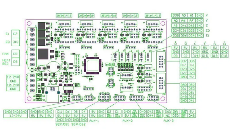
This robot uses an MKS1.4 3D printer shield, which is effectively a dressed up Arduino Mega. Documentation on the MKS can be found here: https://www.roboter-bausatz.de/media/pdf/0b/f0/a7/MKS-Gen-DataSheet.pdf
The following sections will take you through plugging the various electronics components into the main arduino (MKS1.4 board)
Collect 3 of the end stop wiring harnesses:

Cut off ONLY ONE end of the wiring connectors, and strip the last ~4mm of wire:

Solder the cut ends to the end stop, taking care to follow the wiring order as follows: Red to center pin, blue to side where arm connects, black to far right side:

Plug each end stop into the ports on the board and glue in place. Axis 1 (base rotation) should be in Orange slot 1, Axis 2 (main arm motor) should be in blue slot 1, axis 3 in green slot 1.

Connect the motors in the following manner to the board: Axis 1 should be in the red port, with the BLACK WIRE to the far right. Axis 2 in the blue port, and axis 3 in the green port - both with the BLUE WIRE to the far right.